Aircraft components - the wing
For a typical aircraft the following bodies can be identified:
Wings;
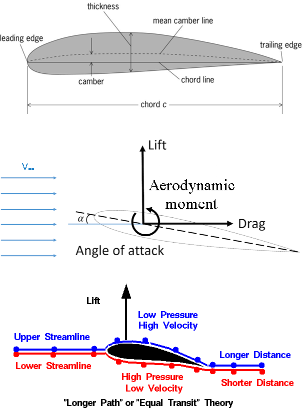
The wings provide the necessary lift to balance the total aircraft weight. It is a box, whose cross-section is called airfoil and it is designed to be streamlined. The airfoil creates the lift because of the air passing the upper and lower surface at different speeds when the aircraft is moving on the ground or in the air. The air speeding around the wing surfaces lead to a drop down into the static pressure which is more pronounce as the airspeed is higher. Therefore, there is a pressure difference around the airfoil. By integrating the pressure along the entire wing, a vertical and horizontal load resultant can be calculated as well as an aerodynamic moment. The vertical load, normal to the wing middle plane, is called lift. The horizontal component oriented opposite the direction of flying is called drag. This component has to be balanced by the thrust created by the engine. The aerodynamic moment is caused by the two loads when reacted at a focal point, typically set at 25% along the chord line measured from the leading edge.
The airfoil and the wing surface are two parameters extremely important as they dictate the wing aerodynamic performances. The principle of lift creation is based on the following remarks:
The airspeed at the leading edge of the airfoil is equals the airspeed at the trailing edge.
As the air passing the upper side of the profile has to pass a longer distance (from the leading edge to the trailing edge) than the air passing underneath, for the same time frame, it means it has to travel faster. Therefore the dynamic pressure is increased Photo1 where ρ is the air density and V is the local airspeed along the streamline).
Then the (simplified) Bernoulli’s principle says that the sum between the static and dynamic pressure is constant. Therefore, when the dynamic pressure increases the static pressure decreases. As the decrease in static pressure is higher on the upper face of the airfoil (and as the static pressure acts perpendicular to any surface) results that the difference between the total static pressure on the lower side and the upper side is a force acting upwards (perpendicular to the airfoil chord line). This force is called lift and for a steady flight it has to balance the weight.
There is an infinite number of possible airfoils. However, they are grouped in few categories mainly based on the flight regime. Therefore, the airfoils used for low speed flights (V < 270mph) are thicker than the ones used for high speed flights and they have a bolded leading edge instead of a sharp one. The airfoil camber is an indicator of the lift potential. Higher the camber, the greater the pressure difference and therefore the lift. However, such a profile induces a higher drag therefore an optimal profile should be selected in order to maximize the lift and minimize the drag depending on the aircraft mission.
The above explanations consider the airplane as a fixed body and the air flowing around. This is a practice used by aerospace engineering.
Wing Airfoil;
An estimation of the total lift for a certain speed is obtained using the following formula:
![]() where:
where:
L is the total lift load
ρ is the air density
V∞ is the airspeed at the leading edge
S is the wing base print area
Cl is the lift coefficient (dimensionless)
In the same manner the drag force and aerodynamic moment are calculated using the following formulas:
![]() ,
, ![]()
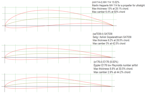
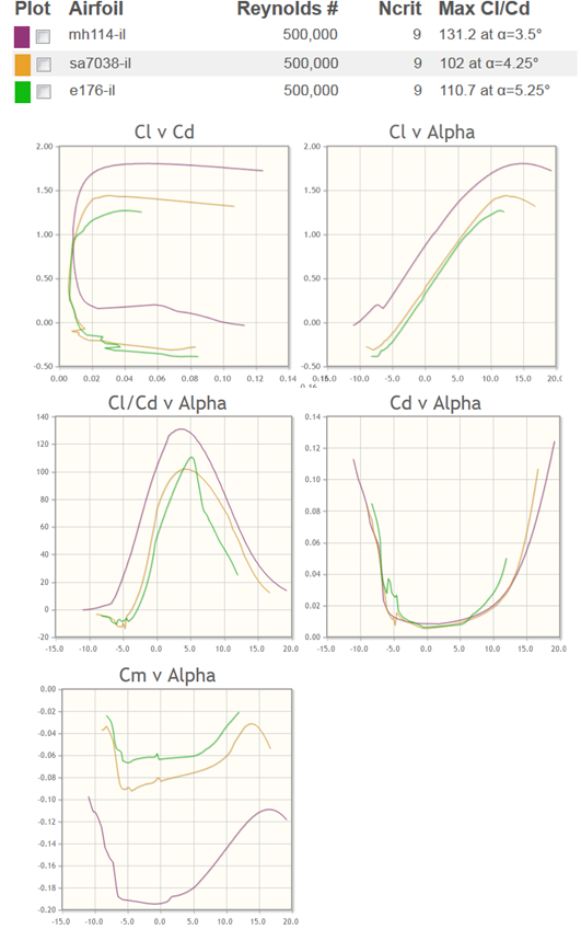
where Cd is the lift coefficient (dimensionless), Cm is the moment coefficient and l is the distance from the pressure centre (where the moment is zero) to the point chosen for resultant load calculation. The lift, drag and aerodynamic moment coefficients are obtained by wind tunnel tests on scalled models, equipped with devices that can measure forces and moments as well as pressure distribution. The following pictures show the variation of these coefficients for different angle of incidence, when three airfoils are considered, mh114 – il, sa7038-il and e176-il.
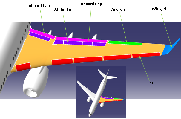
Wing Movables;
On the wing, there are movable surfaces installed meant to increase or decrease the lift force during take-off or landing and to rotate the airplane about its longitudinal axis.
The devices that increase the lift are the slats which are installed all along the wing leading edge and the flaps which are installed in the inboard half of the wing trailing edge. The devices that are meant to decrease the lift are called air-breaks. Typically, they are small flat surfaces placed above the flaps. When used they rise like a wall against the airflow. At the outboard half of the wing trailing edge, there are the ailerons. The ailerons are narrow movable surfaces that are used to control the airplane about its longitudinal axis. The two ailerons placed each wing extremity are meant to work differentially.
For example, when a roll to the right is desired, the aileron on the right wing goes up while the left wing aileron goes down. By going up the aileron decreases the local wing lift. When going down the wing lift is increased. Therefore, this difference creates the necessary rolling moment. At the wing extremity there are winglets that can be installed. They increase the wing performance by reducing the induced drag. The induced drag is caused by the pressure difference between the upper and lower wing surface. At the wing tip the air on the bottom with a higher static pressure tends to move up when the pressure is lower. This movement disturbs the airflow increase the wing drag and decreases the lift. Winglets are installed to prevent this phenomenon.
Wing Internal Structure;
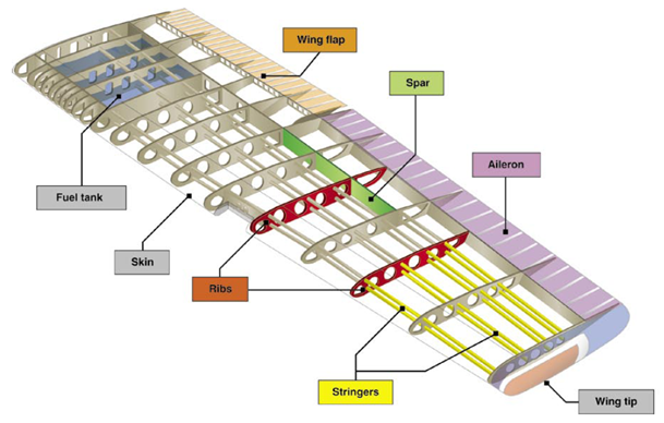
The aircraft structure is a real piece of art. It has to be as light as possible and to resist against any loading that may occur during the aircraft life. The aerospace industry uses specials materials that give the best strength per weight ratio. Therefore, they have to be strong and light, resistant to corrosion and tough, with good fatigue properties as the aircraft structure is exposed to cycling loading.
The internal wing structure mainly consists of spars, ribs and skins.
Commonly, there are two spars, spanning the wing length each side. The front spar is placed at 20- 25% of the airfoil chord from the leading edge. The rear spar is placed at 65 – 75 % of the chord. Together with the skin they form what is called torsion box, and as the name says is useful to resist against wing torsion about the Y axis. This torsion is caused by the aerodynamic moment (air pressure distribution along the airfoil reduced to the focal point) and masses installed with an offset regarding the wing centerline, like engines, landing gear, weapons and the engine thrust. The spars are built to work very well in bending about X axis. They have “I” or “C” section and consist of two flanges (upper and lower) linked by a web. This shape gives a large moment of inertia for a minimum weight. The upper and lower flange work in tension and compression while the web is loaded in in-plane-shear and has to prevent the flanges from separation under axial loading.
The ribs are there to keep the wing from deforming under air pressure. They are very light structure meant to work mainly in in-plane shear. But there are some ribs working as load introduction like the ones serving for engine installation (if there any installed on the wing) or for movable surfaces attachment. These are more robust and more loaded. The ribs are connected to the Skin and the Spars by their flanges or using brackets.
The wing Skin mainly consists of upper and lower skin. They are desired to be as continuous as possible but the manufacturing and assembly processes make it impossible to be a single piece all over the wing. They work in in-plane shear. The skin is just few millimeters and it can buckle. To prevent skin buckling longitudinal stiffeners are attached to the skin with a pitch of about 100 mm. They are called stringers and increase the Skin out-of-plane stiffness. Their cross-section can be “I” or “Z” or “omega”. The rib’s flanges are cut out to let the stingers run all the way from inboard to outboard end.
The wing serves as fuel tank too. The space between the front and rear spar and going over two – three ribs is sealed to work as a tank. Three or four tanks can be built along each wing offering space for tons of fuel. The fuel tanks bring extra benefit to the wings. During the flight the wings tends to bend upward under the air pressure. The more they bend the greater the stresses in the internal structure. Therefore, the fuel tanks add extra weight that prevents the wing from bending excessively.
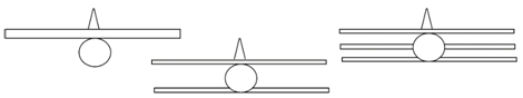
Wing Types;
Considering the number of planes, the wing can be:
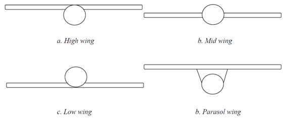
Considering the wing position, relative to the fuselage there is:
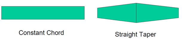
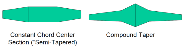
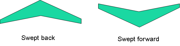
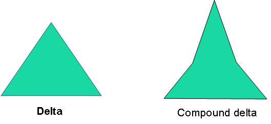
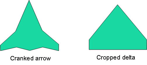
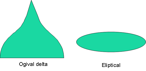
Considering The Wing Shape:
 What Are Seaplanes And Their History Of Development ?
 Interesting Facts You Never Knew About Commercial Aircrafts And Aviation
 Extended Ground Proximity Warning System - EGPWS
 Airspace Classifications And The Air Traffic Control Services
 How An Instrument Landing System ( ILS ) Works
 EFB (Electronic Flight Bag)
 All About Aviation Fuels