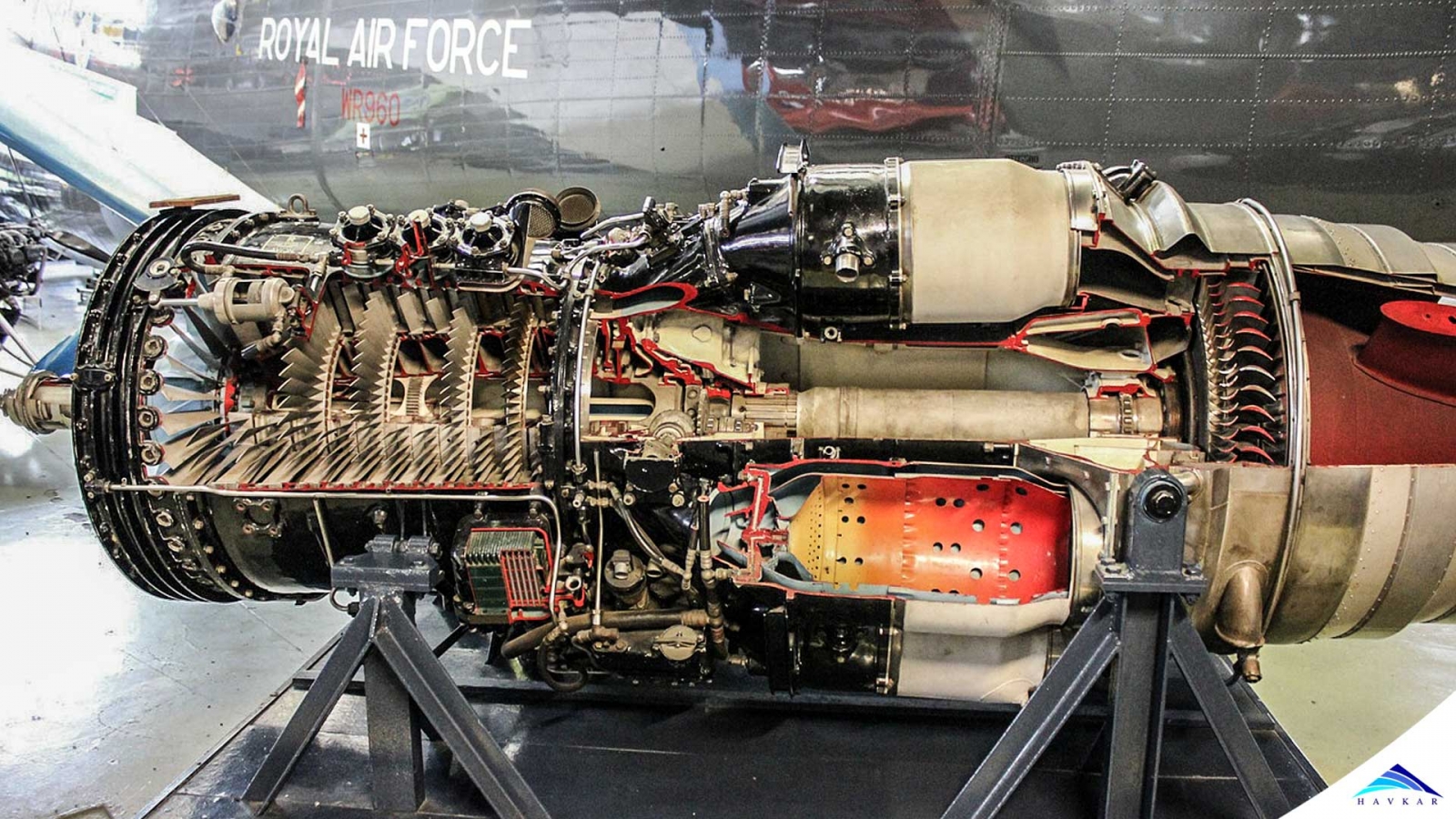
In a turbine engine, compressor aerodynamically performs the function of compressing the air up to the required level as air passes through different stages of it. Just like a fixed wing aircraft, the air flowing through airfoils of different stages of compressor blades of an engine can suffer a stall. When any airfoil suffers such like situation, the compressor becomes less effective thus allowing high-pressure air present behind the stall region, to be pushed forward through the compressor towards the inlet. This is called as reverse flow. This local disruption of airflow is normally called as Compressor Stall.
It may be developed suddenly and is often characterized by an audible symptom as a loud bang. Engine Instruments may show erratic readings in a multiple number of stalls but in case of a single stall, the situation is over so quickly that the instruments do not have time to respond. Hence, compressor stalls range from a single stall, not registering any change on Engine Instruments to a series of stalls leading to a complete loss of compression.
Similarly, a complete disruption in compression resulting in a complete reversal of compressed air flow coupled with the ejection of previously compressed air out from the engine inlet is called as Engine Surge. This situation arises due to compressor’s failure to keep working against the air behind it which had already been compressed and complete loss of compression.
Compressor either faces conditions which supersede the maximum limit of its pressure rise capacities or it is loaded in such a way that it cannot absorb a temporary disturbance, creating a rotational stall. It can further propagate in less than a second to engulf the whole compressor. A stall on the airfoil surfaces of the rotating blades or stationary vanes of the compressor can cause an Engine Surge and a compressor stall situation can get developed on a single compressor blade, vanes or on a group of them.
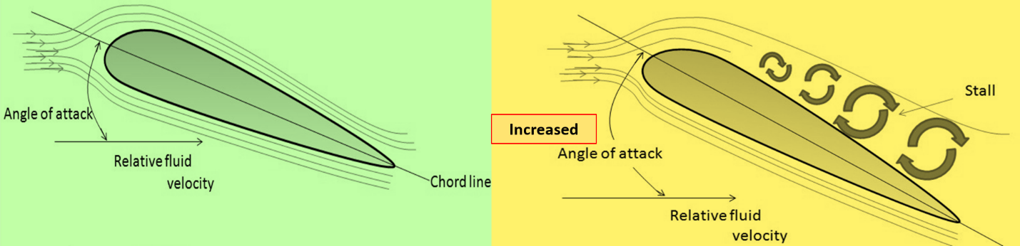
Figure no 1: Airfoil Stall
Causes and Risks;
During early stages of Gas Turbine engines, this was the common problem due to having simple aerodynamics and manual/ mechanical fuel control mechanisms. Modern engines are being designed with a view to minimize chances of developing the conditions that may lead to a surge or stall. But still, a surge/ stall possibility is always present in turbines engines due to Foreign Object Damage (FOD), improper fuel adjustments or malfunctioning of fuel control units. Any time, the pressure in the combustion chamber of the engine increases from the pressure in the diffuser area, an engine surge is going to occur.
Since there is more than one cause for the surge, the resultant sound can range from a single-carburetor backfire type pop to a machine gun rapidity. The noise is accompanied by a very noticeable fluctuation of the engine speed and torque instruments. Repeated surging and the resultant transient torsional loads from the engine can cause damage to the air frame components and so must be avoided. The engine is not usually damaged by a surge unless severe surging occurs, repeatedly. Surging usually indicate that engine operation is not normal, that an investigation should be made to determine the case and steps should be taken to correct the condition before releasing the aircraft for normal operation.
Angle of attack in Turbine Engines;
Surprising for many of us may be to learn that the angle of attack of compressor blades and vanes can change, although they are firmly fixed in compressor rotor disc or stator shrouds. The change in angle of attack takes place when the relationship between the velocity of the air moving through the compressor blades and rotational speed is changed. To understand this relationship more clearly, it is customary to represent the air velocity and rotational speed by arrows or vectors whose length is proportional to the magnitude of the air velocity or rotational speed. The relative velocity is then shown by a vector whose length is determined by the length of the other two vectors. The angle of attack of the airfoil is represented by the angle between the vectors of velocity and relative velocity as shown in the figure below.
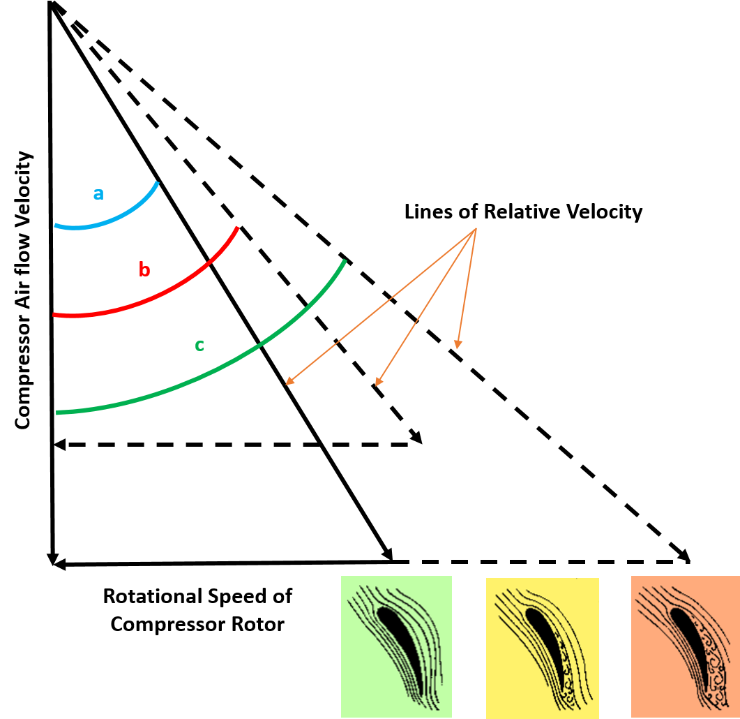
Figure no 2: Effect of the relationship between airflow velocity and rotor speed of the compressor air foils.
In the figure no 2 as given above, angle “a” may be considered as the critical angle of attack of the airflow. This angle of attack may increase beyond the critical point. Angle “b” is the condition when the velocity of the air decreases without a corresponding decrease in the speed of rotation and Angle “c” is the condition when the speed of rotation increases without a corresponding increase in the air velocity. Either of these conditions may induce a compressor stall in a blade or stator vane.
How does it happen in a Turbine Engine?
In order to understand this phenomenon, let us examine the causes and effects of the stall on any airfoil surface. As this is a known fact to many of us, an airfoil is designed with an aim to produce lift by developing a low pressure on the upper surface and a high pressure on the lower side. Every airfoil increases the lift with an increasing angle of attack till it reaches critical angle. Lift quickly deceases if the angle of attack is increased beyond the critical angle of attack. This happens due to the separation of airflow as shown in the Figure no 1. We all are generally known to this condition and its further consequences because it applies to fixed-wing aircraft as well. Compressor stall taking place on a single airfoil of the compressor in a turbine engine is similar to the stall of fixed-wing aircraft.
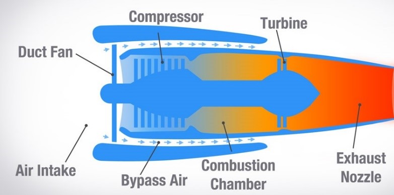
The function of the compressor section of a gas turbine engine is to deliver the required amount of atmospheric air to the combustor section at the required elevated pressure and to do this as efficiently as possible. The compressor is able to raise, by some incremental amount, the pressure level of the air as it passes through each individual stage of the compressor. It does this by proper utilization of the characteristic ability of the airfoil-shaped blades and vanes to produce lift.
Just as the lift produced in a fixed (rotary) wing supports the weight of the aircraft against gravitational forces, the sum of all the incremental lifts produced by the airfoil sections within the combustor support the high-pressure reservoir of air within the combustor section. As long as nothing happens to upset the lift-producing capacity of the blades or vanes, high-pressure air will flow from the compressor into the combustor at the same rate at which it flows out through the turbines and a state of delicate balance will be maintained. If a sufficient number of blades or vanes within the compressor undergo a stall, then this state of balance can no longer be maintained. The high-pressure reservoir of air in the combustor tends to discharge air forward through the compressor and it causes a momentary airflow stoppage. When this state happens, the engine is said to be in a surge. The discharge of the high-pressure reservoir in the combustor completely unloads the compressor and un-stalls the airfoils for the time being. The compressor builds up the back pressure to the point where stall and the resultant surge may again occur, repeatedly.
Engine Surge Line and Operating Line;
Lower Limit of the operating region, in which an engine can operate reasonably well with satisfactory performance is called as Engine Operating line. The boundary of the operating region where engine surge can occur may be precisely located and is known as Engine Surge Line. For the most efficient gas turbine engine operation, it is desirable to operate as close to the surge line as possible but without the danger of the engine surge under any specified operational or environment conditions.
Surge Margin;
Surge margin is defined as the distance or region of normal operation between the normal Engine Operating Line and the Surge Line.
Varying the Engine Operating Line;
Surge line of a particular compressor of a turbine engine is basically fixed as a design feature. The engine operating line can be varied by several conditions. Most significant of all the conditions are mentioned as under:
Anti-Surge/ Stall Measures;
a. Variable Inlet Guide Vane (VIGV) System
To provide a surge margin, the angle of incident of the inlet air to the first compressor rotor must be within the stall-free operating range of the transonic airfoil (first two stages of the compressor). Since this stall-free operating range varies with compressor speed, it becomes necessary to vary the angle of attack as the function of the compressor speed. This is accomplished generally by varying the angular position of the inlet guide vane. The variable inlet guide vane is located in front of the first compressor rotor and consist of a series of hollow blades positioned by a synchronizing ring.
The variable inlet guide vanes match the angle of inlet between inlet air and the first compressor rotor blades to maintain the airflow requirements of the compressor rotor assembly. At low gas turbine speeds, a high angle of the inlet is required while at higher compressor speeds, the angle of inlet required decreases accordingly. Since it is the proper inlet airflow angle relative to rotor speed that we are concerned with. Inlet guide vanes must vary in position as a function of compressor rotor speed and air temperature.
b. Inter-stage Bleed band System
This system is supplied with the turbine engine to improve compressor acceleration characteristics. The system automatically relieves the compressor of a small amount of air (about one tenth) during the period in the engine acceleration cycle when faster compressor acceleration is more desirable than a slight loss of engine power due to air bleed. On a standard day, the bleed bands normally get opened at compressor speeds below 70-80% and get closed during acceleration above this value to ensure a stall-free operation of a turbine engine.
Remedial Measure;
If engine surge should occur during engine run-up or flight, the engine may be brought out of the surge by an immediate reduction of fuel flow as a general rule. This may be done by using the throttle to reduce power slightly. An investigation should then be made to determine the cause of surge so that corrective action can be taken as per applicable Engine Maintenance Manual.
 What Are Seaplanes And Their History Of Development ?
 Interesting Facts You Never Knew About Commercial Aircrafts And Aviation
 Extended Ground Proximity Warning System - EGPWS
 Airspace Classifications And The Air Traffic Control Services
 How An Instrument Landing System ( ILS ) Works
 EFB (Electronic Flight Bag)
 All About Aviation Fuels