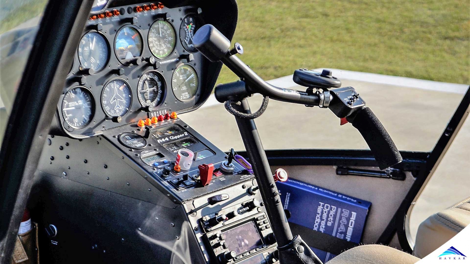
Each of these is a system of mechanical linkage, assisted by hydraulic cylinders, connecting the pilot and gunner control sticks and pedals to those mechanisms which rotate with and directly control the main rotor and tail rotor. Normally, main rotor cyclic and tail rotor controls incorporate electrically operated magnetic brakes and force trims to steady the stick and pedals against movement of their own accord and to induce artificial control feel to the pilots.
With the latest trends in aviation technology, nowadays all helicopter operators are enjoying the luxury of state of the art autopilots as latest as four degrees of freedom. Today, we are going to have the look of a system which was in place before the invention of an autopilot. This system used to give the stability to the helicopters along with augmenting the control inputs to a comfortable level for pilots. The system was commonly known as Stability and Control Augmentation System (SCAS) and was incorporated in helicopters designed/ manufactured in the late 60s and early 70s as well.
Introduction;
The main rotor cyclic and tail rotor controls incorporate stability and control augmentation system (SCAS). The operator has the option to use or turn it off at the SCAS control panel. Said system employs an electronically controlled, hydraulically actuated linkage in the cyclic and anti-torque systems to provide stability and control augmentation to the pilots. It also incorporates an armament compensator unit if it’s installed in a gunship helicopter.
Components;
Basic components of a SCAS are mentioned as under:-
System Description;
The SCAS receives 28 V DC power from the essential dc bus through the circuit breaker. When the SCAS is engaged, 28 V DC power is mostly supplied by the battery so that loss of power to the essential dc bus will not disengage SCAS. AC power is supplied by the 115 V ac essential bus. All the Line Replaceable Units and components are inter-connected with colour-coded wires for transferring the signals and power within the system.
Hydraulic power is provided to the longitudinal and lateral electro-hydraulic servo actuators by the standby hydraulic system while the directional electro-hydraulic servo actuator is supplied by the main hydraulic system.
Servo-actuator assemblies are three in number usually, one control tube is attached to one end and on the other end, a clevis is attached to each of the servo actuators. Both of these, provide a mounting to the servo actuators in series with mechanical controls of the helicopter. The internal piston and shaft of the actuator hydraulically move in and out of the actuator case to provide for mechanical displacement of helicopter controls. A solid link is provided in helicopter’s controls linkage by internal centring and locking mechanism in case hydraulic pressure to the actuator is lost or even if a channel gets disengaged. An internal servo-hydraulic valve is provided for controlling hydraulic pressure to the piston in the proper direction of displacement.
Servo actuators are electro-hydraulically operated and receive command signals from sensor amplifier unit to hydraulically driven helicopter control system. Servo actuators are limited to a total +/- 10-15 % of total pilot control authority. Pitch and roll servo actuators control movement of the swash plate with no resultant motion of the cyclic stick as a result of external forces. Yaw servo actuator moves the tail rotor blade pitch angle in the same manner as pitch and rolls servo actuators move helicopter swash plate. Yaw servo actuator control authority is also limited to +/- 10-15 % of control authority available to the pilot through control pedals.
A force gradient is incorporated in order to give an artificial feeling to the pilot with a magnetic brake to lock the controls in any specified position during flying operation, in order to lessen the workload on flying crew.
Any external disturbance is sensed by three-axis rate gyros by helicopter’s motion and is sent to the SAU which further sends a signal to control motion transducers and actuators to immediately correct or nullify the disturbed position of the helicopter without any pilot input.
The armament compensator unit supplies signals to each sensor amplifier module (SAM) when the guns or weapons are fired in order to provide the stability by dampening the vibrations to be caused by the said reason.
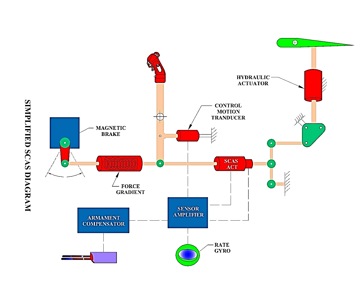
Figure 1: SCAS Block Diagram
SCAS Control Panel;
This panel consists of a mounting plate, an integrally lit panel, one power switch, three engage switches, three press-to-test amber NO GO indicator lights that can be dimmed by turning the light cover, four spring lock fasteners to provide for console mounting and one cable assembly.
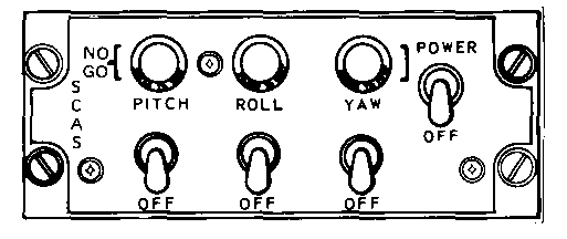
Figure 2: SCAS Control Panel
It applies 28 volts dc and 115 volts ac to the SCAS components when setting to Power position. Disconnects power when set to OFF.
These switches engage pitch, roll, and yaw channels and servo-hydraulic solenoids on the actuators when set to pitch, roll, or yaw position. The channels are disengaged when the switches are set to OFF.
When the lamps are lighted, they indicate an out of tolerance system condition or an unexpired warm-up period. The system should not be engaged in this condition.
Sensor Amplifier Unit;
The sensor amplifier unit (SAU) contains three sensor amplifier modules (SAM), one each for Pitch, Roll and Yaw channel. The front of each module contains two push buttons labelled as Rate Test, Actuator Test and a Null light. Each SAM is held in place by four captive screws. These switches segregate the input from rate gyros and servo actuators in combination with Built-in test equipment facility. When either main or standby hydraulic pressure is lost, the respective hydraulic pressure switch will close to further lose the pressure. This illuminates the caution light of system which failed and disengages the sensor amplifier module(s) (Yaw or Pitch and Roll) relay(s) circuit thus disengaging the affected channel servo actuator of the system.
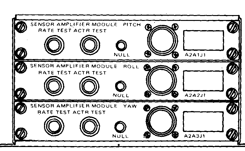
Figure 3: Sensor Amplifier Unit
Electro-Hydraulic Servo Actuator;
Each stabilized channel has an electro-hydraulic servo actuator which will be referred to as servo actuator. It extends or retracts control linkage in which it is installed to move the swash plate or change the pitch of the tail rotor. Each servo actuator contains motion feedback transducer which informs the compensation network (within each SAM) of the servo actuator position. Extension or retraction of the servo actuator is not felt in the pilot flight controls provided proper control friction is present. The actuator will be mechanically locked in centred position when in a de-energized position. Applying hydraulic pressure by engaging the channel retracts the locking mechanism and readies the servo actuator for valve drive commands.
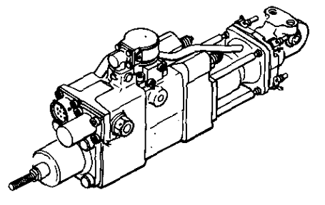
Figure 4: Electro-Hydraulic Servo Actuator
Control Motion Transducer;
The control motion transducer consists of an internal linear potentiometer (variable resistor), a cylindrical case, a movable shaft (rotation of the shaft will not affect resistances), two attachment points (one on the case and one on the shaft) and a connector for transferring signal data and power. Control motion transducers are mechanically connected to the controls and used to indicate control movement by the pilot the sensor amplifier channels.
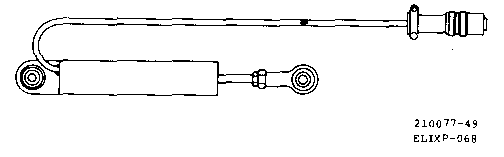
Figure 5: Control Motion Transducer
Three - Axis Rate Sensor;
There are three - axis rate sensors which will be referred as a three-axis sensor from here onwards. It consists of a mounting surface, one cable assembly and one connector. Three rate gyros within the package sense helicopter rates in each of the three stabilized axes. Electrical rate signal outputs from each of the rate gyros are applied to each of the sensor amplifier modules compensation and logic networks.
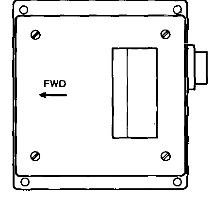
Figure 6: Three - Axis Rate Sensor
Armament Compensator Unit (ACU);
This is part of the overall system only in case of Gunship helicopters. Three-axis turret position signals are applied to the ACU when the weapon is fired to provide weapon recoil damping of helicopter movement. This unit is electrically interfaced with any weapon system and SCAS. Weapon position signals are applied to the Armament Compensator Unit and when the weapon is fired, output signals are applied to the SCAS servo actuators to provide recoil dampening.
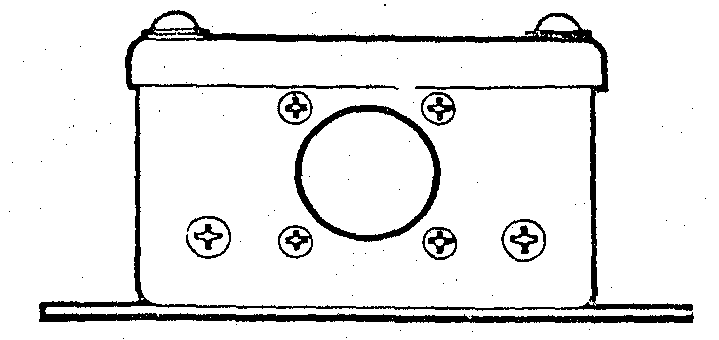
Figure 7: Armament Compensator
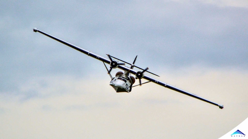 What Are Seaplanes And Their History Of Development ?
 Interesting Facts You Never Knew About Commercial Aircrafts And Aviation
 Extended Ground Proximity Warning System - EGPWS
 Airspace Classifications And The Air Traffic Control Services
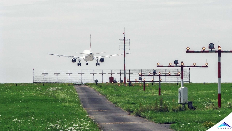 How An Instrument Landing System ( ILS ) Works
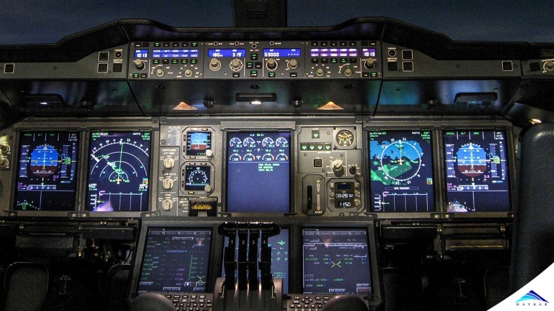
 EFB (Electronic Flight Bag)
 All About Aviation Fuels