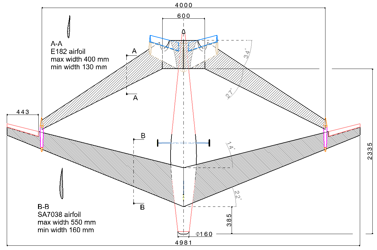
Overall dimensions wingspan 4 m.
Airfoil maximum width 0.5 m
Cruise speed 10-15 m/s
Never exceed speed 30 m/s
Maximum takeoff weight 25kg
Mission equipment weight maximum 5 kg
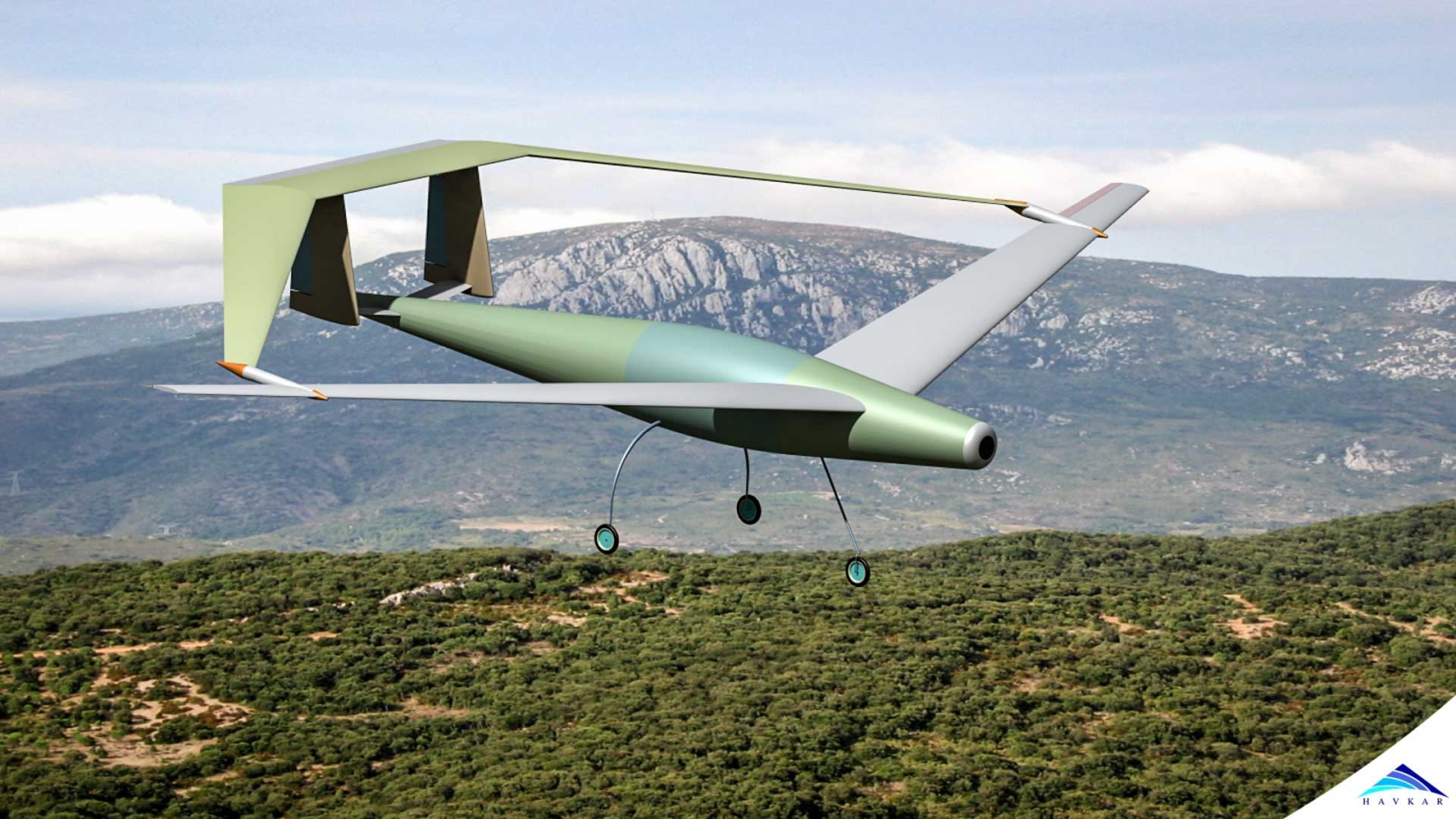
The structure has to be as light as possible given its maximum takeoff weight of only 25 Kg and its size. A wing box is a good solution because the wing can be less stiff as the two wings are supporting each other and therefore lighter. The tail must be capable of supporting the rear wing therefore a double vertical stabilizer is considered. The airfoil should be suitable for low airspeed and must be capable of producing the required lift with minimum drag.
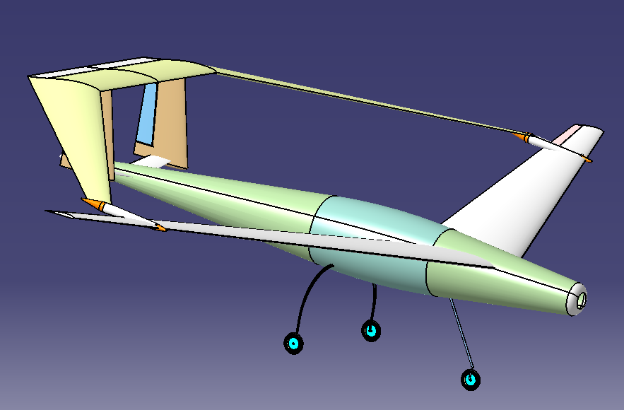
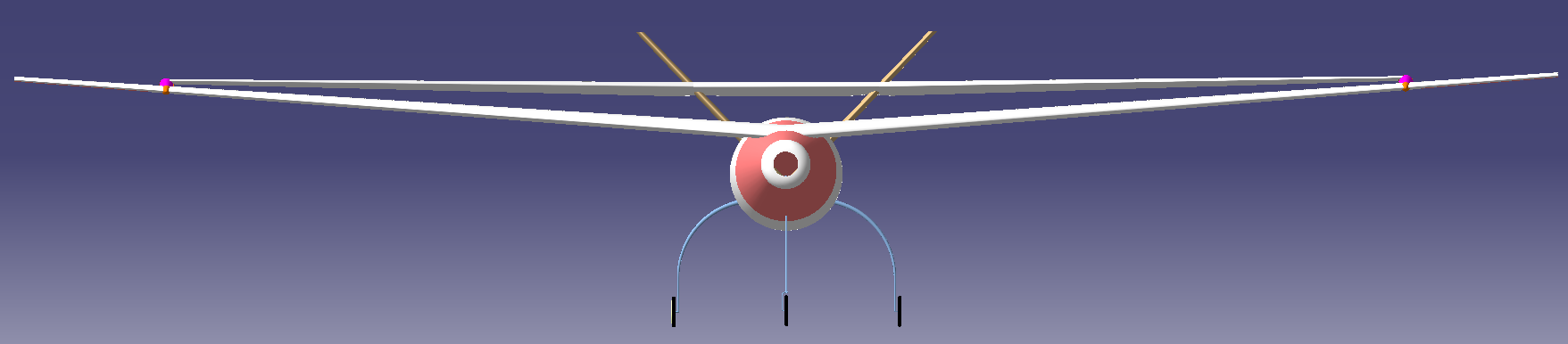
Isometric view (from top)
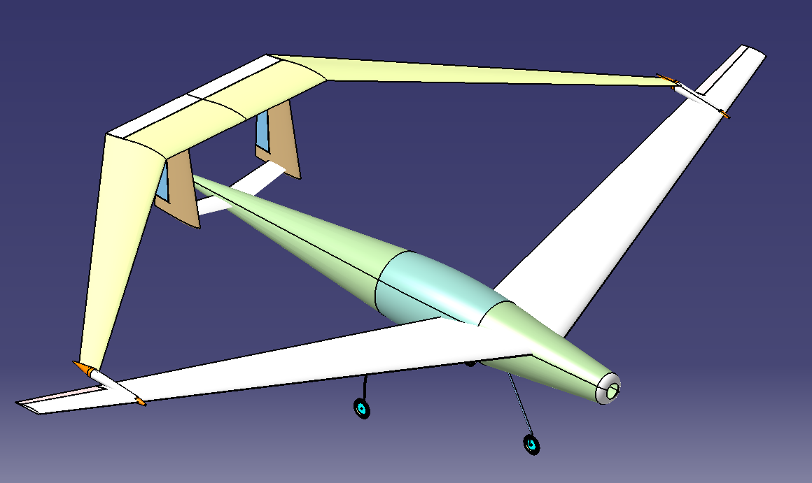
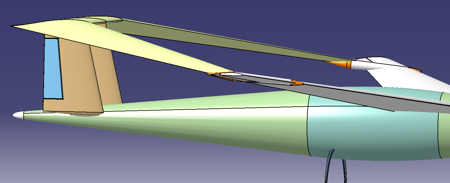
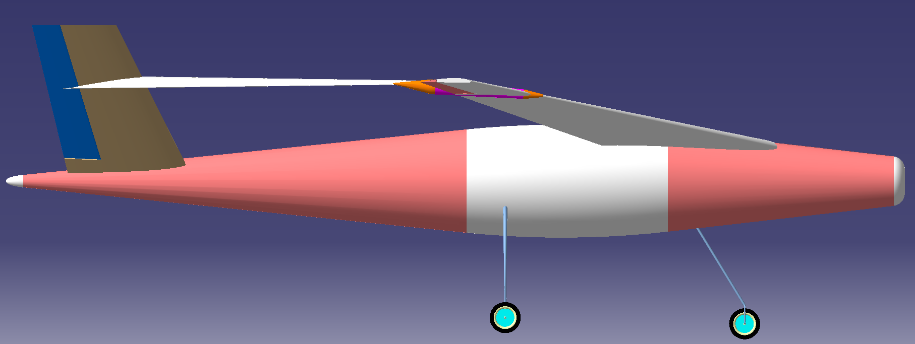
Isometric view (from lateral-top)
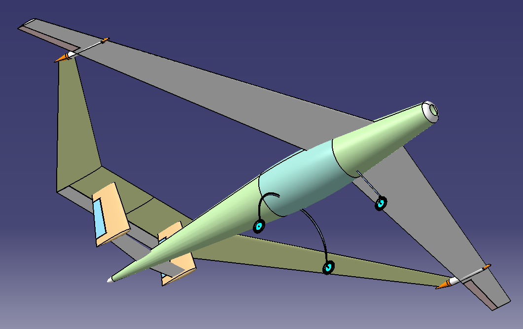
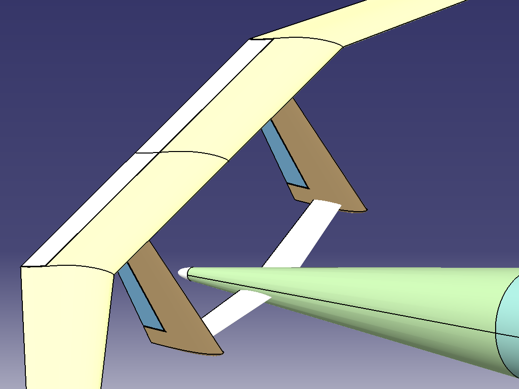
Isometric view (from bottom)

Isometric view (from bottom)
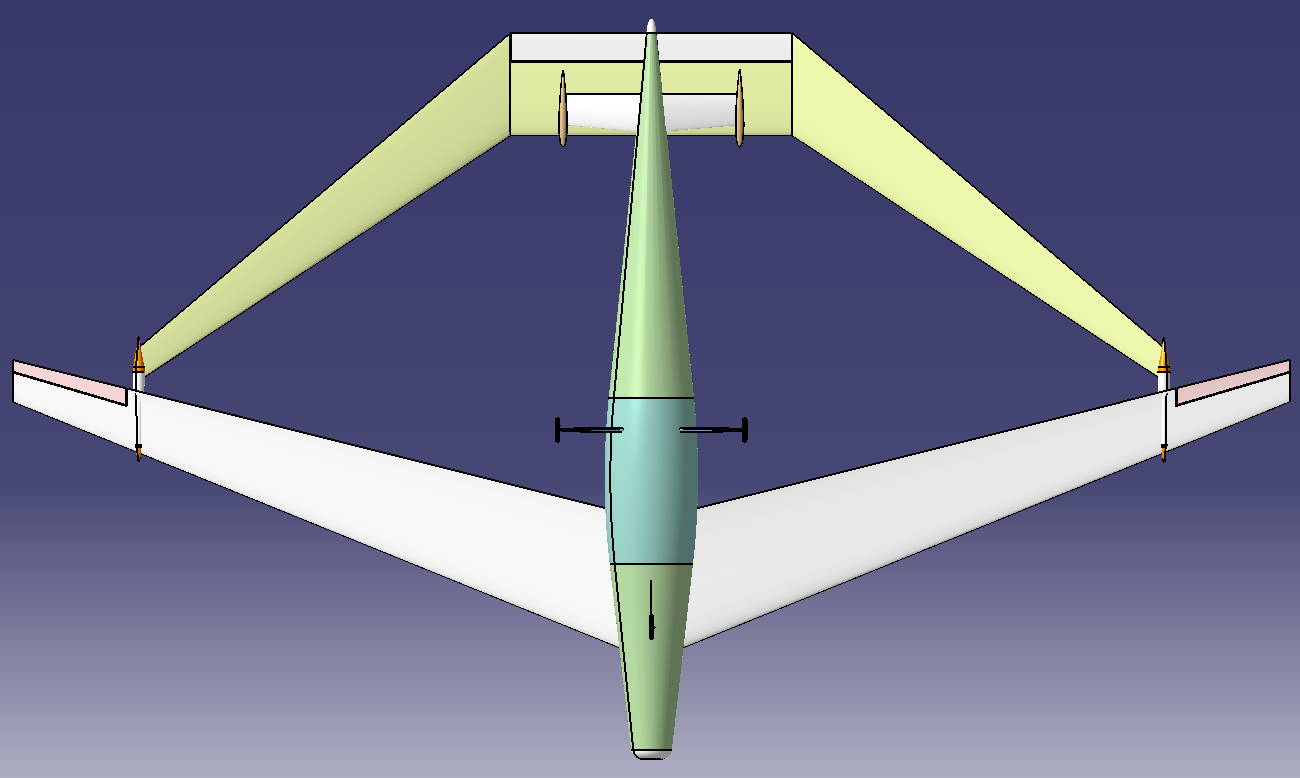
Bottom view
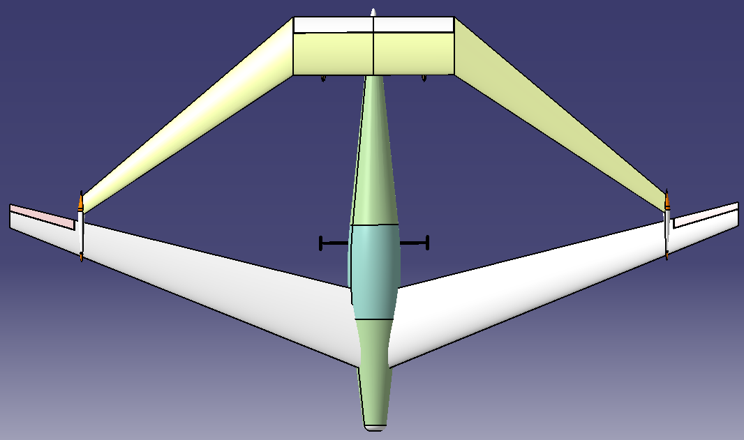
Top View
The principle of lift creation is based on the following remarks:
The airspeed at the leading edge of the airfoil is equal with the airspeed at trailing edge.
As the air passing the upper side of the profile has to pass a longer distance (from the leading edge to the trailing edge) than the air passing underneath, for the same time frame, it means it has to travel faster. It means further that the dynamic pressure is increased ( ![]() where ρ is the air density and V is the local airspeed along the streamline).
where ρ is the air density and V is the local airspeed along the streamline).
Then the (simplified) Bernoulli’s principle says that the sum between the static and dynamic pressure is constant. Therefore when the dynamic pressure increases the static pressure decreases. As the decrease in static pressure is higher on the upper face of the airfoil (and as the static pressure acts perpendicular to any surface) results that the difference between the total static pressure on the lower side and the upper side is a force acting upwards (perpendicular to the airfoil chord line).
This force is called lift and for a steady flight it has to balance the weight.
There is an infinite number of possible airfoils. However they are grouped in few categories mainly based on the flight regime. Therefore the airfoils used for low speed flights (V < 270mph) are thicker than the ones used for high speed flights and they have a bolded leading edge instead of a sharp one.
The airfoil camber is an indicator of the lift potential. The higher the camber, the greater the pressure difference and therefore the lift. However such a profile induces a higher drag therefore an optimal profile should be selected in order to maximize the lift and minimize the drag.
My feeling is that a profile with a maximum thickness of 12-15% of the chord, placed at about 25 % from the leading edge and with a camber of about 3% of the chord, will fit well for this project. Therefore I will have a look into the airfoil categories that are close to these specifications.
Furthermore the lift has to balance about 25kg at a minimum speed of about 10 m/s considering the wing base print surface of about 1, 78 m2 for front wing and 1, 14 m2 for rear wing. An estimation of the total lift for a certain speed is obtained using the following formula:
![]()
L is the total lift load (25 kg)
ρ is the air density (≈1Kg/m3)
V∞ is the airspeed at the leading edge (minimum 10 m/s)
S is the wing base print area (1, 78 m2 for front wing and for 1,14 m2 rear wing)
Cl is the lift coefficient (dimensionless), deduced by experiments
Therefore a profile that can ensure a Cl of about 0,2 for an angle of incidence (α) close to zero (considering the airspeed 10 m/s) is needed.
An airfoils that is frequently used for gliders and motorized gliders construction is Selig / Ashok Gopalarathnam SA7038. The airfoil MH114 has even better lift/drag ratio.
For the airfoil of the wing I will make a choice between the following four profiles:
Each of these four is a good fit for low speed flights (low Reynold’s number).
The Reynolds’s number is defined as;
![]()
Where:
ρ is the density of the fluid (SI units: kg/m3) – in our case 1
u is the velocity of the fluid with respect to the object (m/s) - 10 minimum/30 maximum.
L is a characteristic linear dimension (m) – 0,35 m (average airfoil width) for front wing and 0,265 m (average airfoil width) for rear wing
ν is the kinematic viscosity of the fluid (m2/s) - 1.5111E-5 for ambient temperature of 20°C.
Therefore ![]() (considering the front wing).
(considering the front wing).
Given the above remarks I chose profile SA7038 for the front wing and E182 for rear wing. They provide sufficient lift while maintaining the drag low and allow a good manoeuvrability for such a large wing.
The wing has a box wing configuration. It consists of two opposite swept wings. The front wing has a base print area of 1, 78 m2 and a swept angle of 22°. The airfoil for this is SA7038 with a maximum width of 550 mm and a minimum of 160 mm. It is installed on the fuselage with 0° initial angle of incidence and a dihedral angle of +5°. Due to the landing gear position the front wing has an angle of incidence of +1,5°. The dihedral angle increases the stability about the roll axis; therefore the plane is more stable when considering significant lateral winds. At the front wing tip there are ailerons installed (450 mm * 40 mm – 25% of the wing width) in order to control the plane about roll axis. The rear wing has a base print area of 1,14m2 and a swept angle of -34°. The airfoil for this is E182 with a maximum width of 400 mm and a minimum of 120 mm..
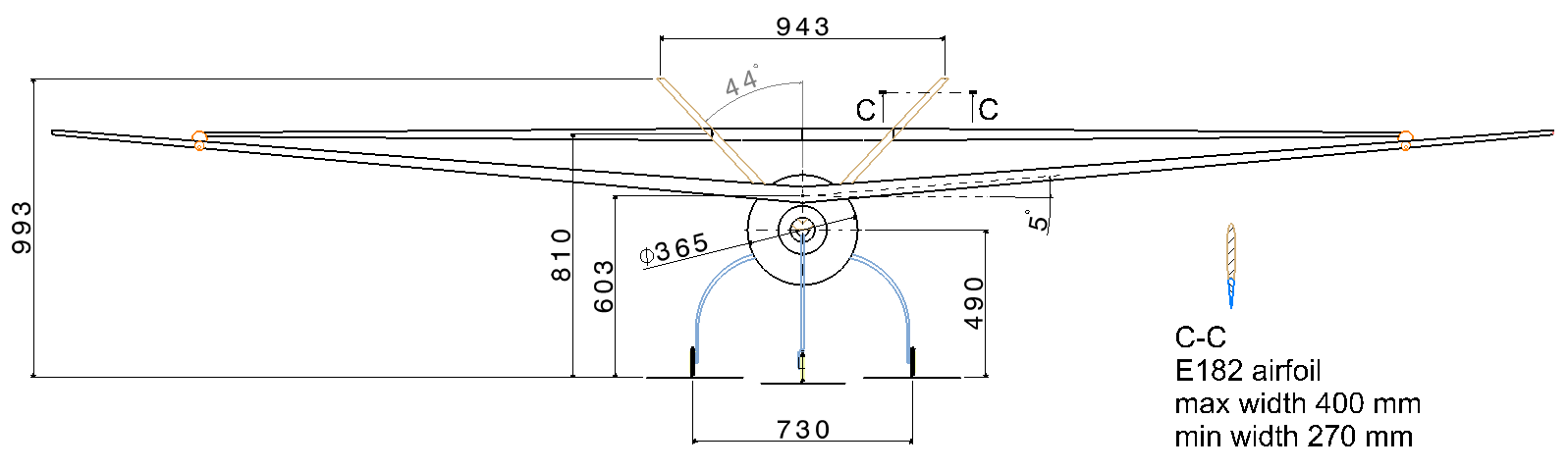
The tail of the airplane is placed at about 1,5 m far from the expected centre of gravity. This is because the large wing require large efforts (moments) to manuver the plane. It as a V shape with two surfaces placed at 44° to the symmetry plane. It is used to control the plane about pitch and yaw axis. Therefore by turning the two mobile surfaces in opposite direction they act like an elevator controlling the balance against pitch axis. Otherwise when the mobile surfaces turn in the same direction they act like a double rudder, controlling the plane in yaw direction. The tail consists of Naca 0010 airfoil. Each surface has a trapezoidal shape; 500 mm in height, 400 mm the highest width and 270 mm the smallest width. The rudder has a trapezoidal shape too. The moving surfaces at the trailing edge are 30% of the airfoil width. They are continuous over the rear wing.
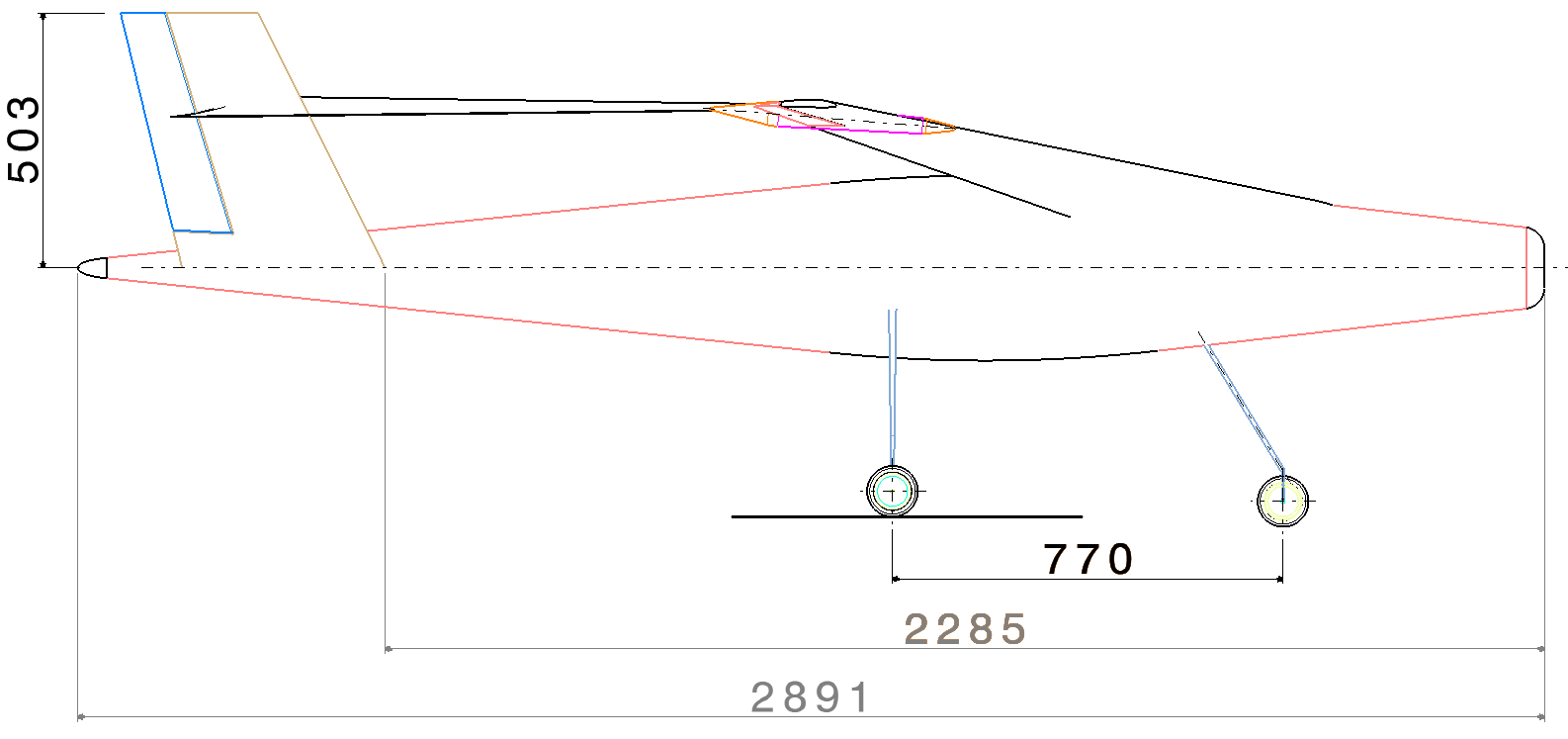
The fuselage has a simple design that to induce as small drag and ensure enough room to accommodate the electric motor, the batteries and the mission equipment. The overall dimensions of the fuselage are: 2890 mm in length with a maximum section of 365 mm in diameter.
The landing gear is designed to be light and to allow primitive means of shock absorbing. It consists of main and front landing gear. It has three wheels (main landing gear and a nose wheel). The wheel diameter is about 100 mm. It ensures a distance of about 310 mm from the bottom of the fuselage to the ground and a distance of about 490 mm from the propeller axis to the ground level. The spacing between front and main landing gear is 770 mm. The distance between the two wheels of the main landing gear is 730mm. Its position ensures an angle of incidence for the wing of about 1, 5° during the take off.
The plane can be equipped with a 25’’ - 30’’ propeller (600 – 750 mm in diameter – it will not touch the ground).
An estimation of the required engine thrust is performed hereafter.
The thrust has to balance the total drag. The drag force is calculated using the following formula:
![]()
Where Cd is the drag coefficient (dimensionless), deduced by experiments (see annex A and B).
For a flight at 10m/s:
Drag from the front wing: Dfront_wing = 1,34 Kg
Drag from the rear wing: Drear_wing = 0,85 Kg
Drag from the tail: Dtail = 0,48 Kg
Drag from the fuselage: Dfuselage: 0,75 Kg (0,15 drag coefficient has been considered).
Total drag: Dtotal = Dwing + Dtail+ Dfuselage = 3,42 Kg.
This is the theoretical drag caused by the (assumed) laminar airflow. Extra drag is created by the air to surfaces friction. Also the induced drag will count (in a small quantity given the large wingspan, the winglet presence and the low flight speed). 20 % drag increased is considered to the theoretical value due to air friction and induced drag.
Therefore the necessary thrust for a flight at 10 m/s is 4,1 Kg.
For a flight at 20m/s:
Drag from the front wing: Dfront_wing = 2,14 Kg
Drag from the rear wing: Drear_wing = 1,14 Kg
Drag from the tail: Dtail = 0,96 Kg
Drag from the fuselage: Dfuselage: 3 Kg (0,15 drag coefficient has been considered).
Total theoretical drag: Dtotal = Dwing + Dtail+ Dfuselage = 7,24 Kg.
20 % drag increased is considered to the theoretical value due to air friction and induced drag.
Therefore the necessary thrust for a flight at 20 m/s is 8,7 Kg.
For a flight at 30m/s:
Drag from the front wing: Dfront_wing = 3,41 Kg
Drag from the rear wing: Drear_wing = 1,79 Kg
Drag from the tail: Dtail = 2,16 Kg
Drag from the fuselage: Dfuselage: 6,75 Kg (0,15 drag coefficient has been considered).
Total theoretical drag: Dtotal = Dwing + Dtail+ Dfuselage = 14,1Kg.
20 % drag increased is considered to the theoretical value due to air friction and induced drag.
Therefore the necessary thrust for a flight at 30 m/s is 16,9 Kg.
As a conclusion the power needed for a flight at 30 m/s is very high. Such a thrust requires large amount of energy, therefore it can’t be sustained for too long. This speed is more like never exceed speed. It will be achieved when flying on a steep slope and it is useful as a limit for the structure ultimate strength.
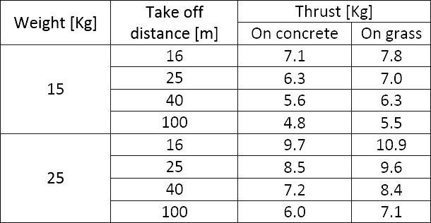
An estimate is done regarding the necessary thrust when a desired takeoff distance is established.
The equation to be used to determine the necessary thrust during takeoff is the following:
T – D –F = ma,
or
T – D –Wµ = ma
Where:
T the necessary thrust
D the airflow drag
F the friction between landing gear and the ground
m the airplane mass
a the desired acceleration
W the airplane weight (15 Kg /25 Kg)
µ rolling friction coefficient (0,015 on concrete and 0,06 on grass)
The take off speed is 10 m/s. It means that with a constant acceleration of 2m/s2 the airplane reaches the take off speed in 5 seconds. Per these conditions the airplane moves on a distance of 25 m.
Note: In reality the acceleration is not constant due to the fact that the drag force increases nonlinear with the airspeed.
Assumption: For this analysis the drag force is considered constant at 75% from the value reached at 10 m/s (4,56 Kg), therefore D = 3,1 Kg.
The following table shows the required thrust for various configurations.
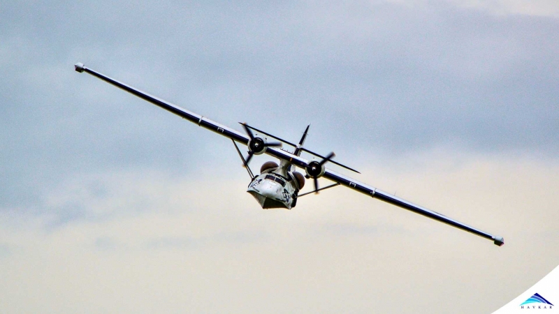 What Are Seaplanes And Their History Of Development ?
 Interesting Facts You Never Knew About Commercial Aircrafts And Aviation
 Extended Ground Proximity Warning System - EGPWS
 Airspace Classifications And The Air Traffic Control Services
 How An Instrument Landing System ( ILS ) Works
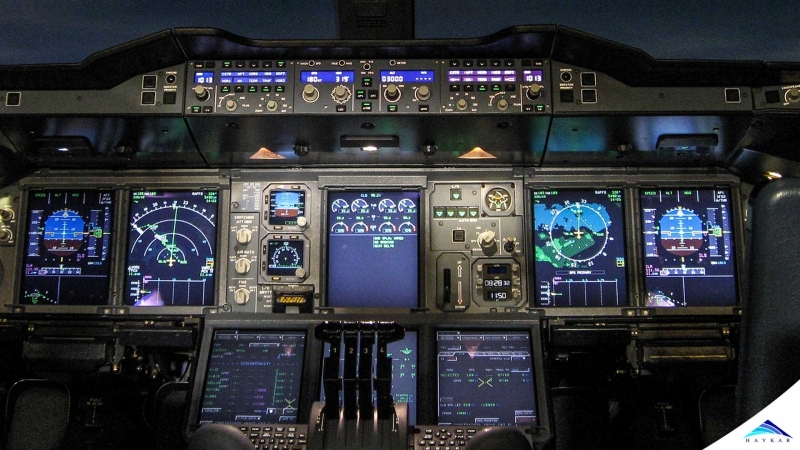
 EFB (Electronic Flight Bag)
 All About Aviation Fuels