Oil System;
Similarly, Transmissions of helicopters normally have their own lubrication system and functions of which include lubrication, cooling and internal cleaning of internal components. Level of oil is checked through a sight gauge which may be two or more at different locations depending upon the design of a specific transmission. Many main gearboxes have chip detectors as well, located at sump for detection and early warning of the wear and tear of internal components. Chips detectors are electrically connected to warning lights in the pilot’s instrument panel that light up to warn pilots in the event of an internal failure/ wear and tear happening inside the gearbox/ transmission assembly. In modern helicopters, chip detectors may have a burn-off capability which may correct the situation without a pilot action or remedial measure. Otherwise, pilot has to refer to the specific emergency procedure of that helicopter in order to decide further course of action.
Functions;
Main purposes which a Transmission serves in a helicopter are given as under :
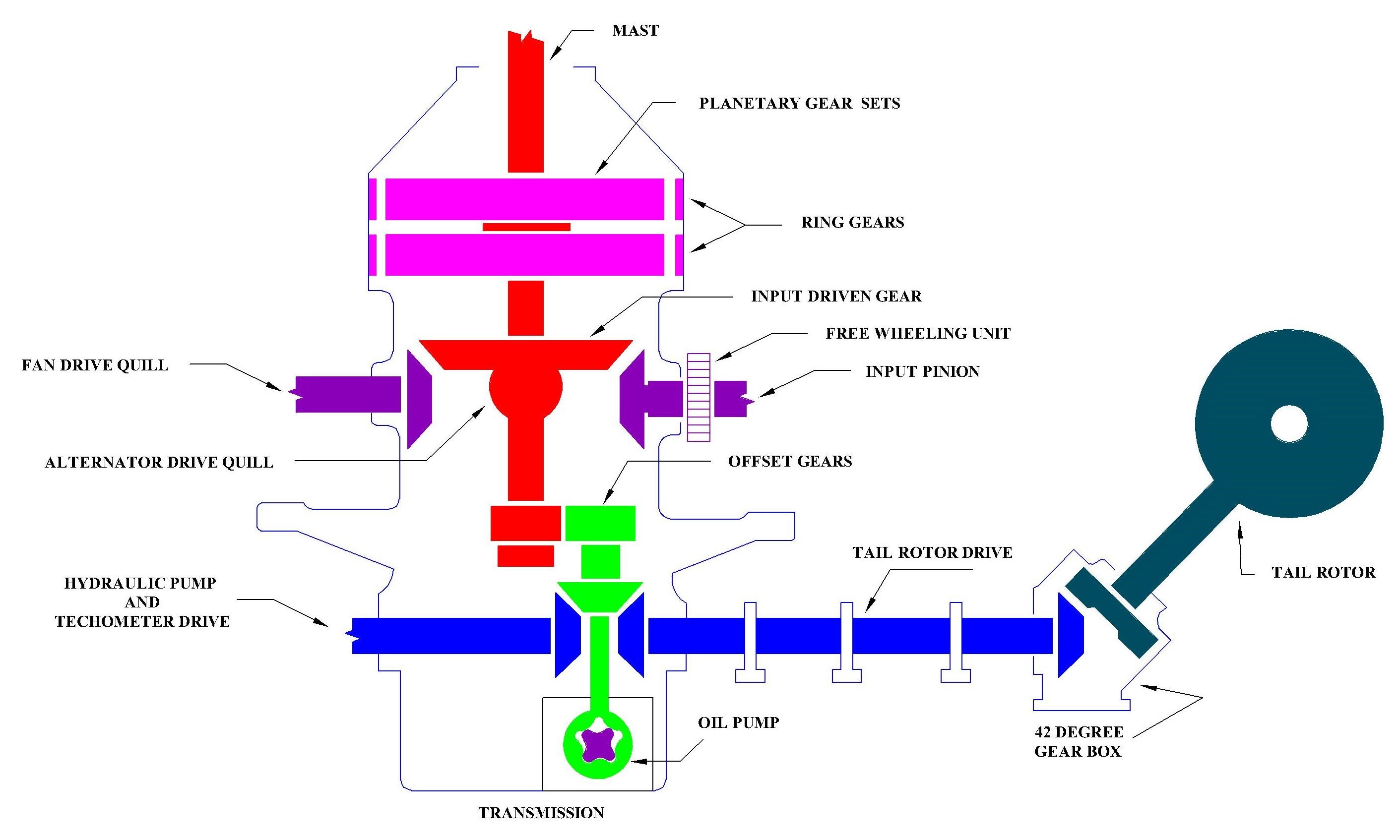
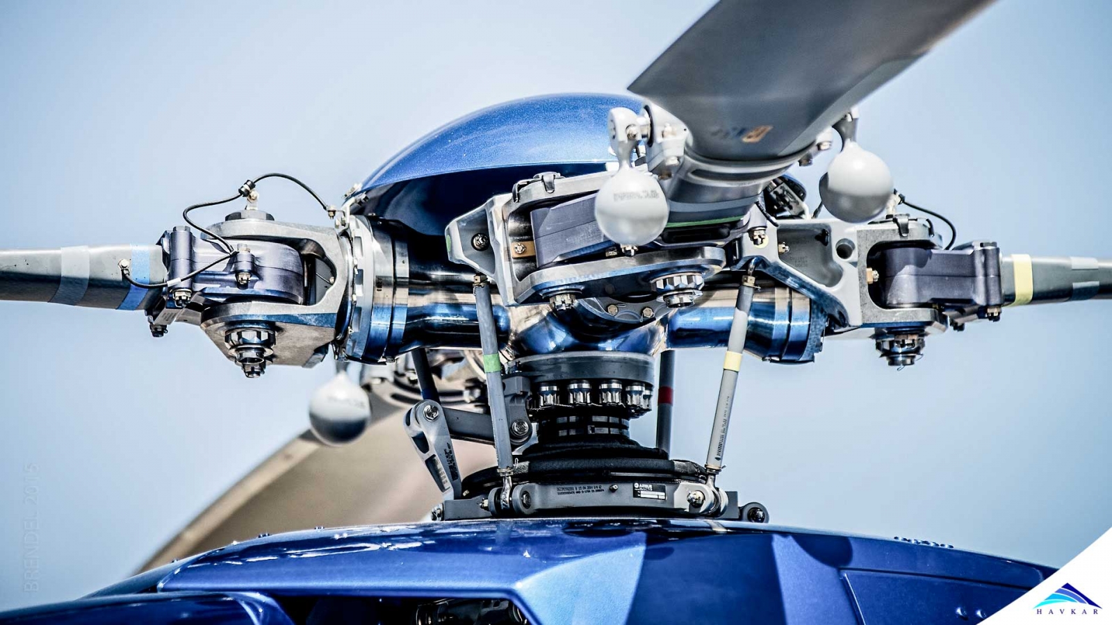
Figure 1: Main Gearbox and Drive System of a helicopter.
Operation;
Statically, the transmission supports the weight of the mast, the rotating controls, and the main rotor. In flight, the transmission along with the mast is the main and the only link between the main rotor and the airframe. Output reduction ratios vary with design of transmission. Engine rpm is reduced to main rotor rpm through internal transmission gear reduction. This reduction is generally accomplished by a system of bevel gears and a two-stage planetary, for an increased overall reduction of rpm for main rotors.
Engine is directly connected to the transmission by a shaft, normally called as the main drive shaft. The main drive shaft, also known as a short shaft, connects the engine to the freewheeling clutch portion of the transmission input quill. The input quill pinion drives the horizontal spiral bevel gear, providing the first stage of reduction. The horizontal spiral bevel gear drives the cockpit air blower along with other accessories and vertical shaft. Through the vertical shaft, torque is transmitted up to the two-stage planetary gears and to the mast assembly.
Freewheeling Unit;
The function of a Clutch or Freewheeling Unit is to disengage the main Transmission drive from the engine to allow free rotation of main rotors and also the drive to tail rotor system in case of an Autorotation. The freewheeling unit may be located in the accessory gearbox in some helicopters as it is a part of helicopter transmission or it may be a part of engine accessory gearbox in some cases.
Main Sections;
Generally, the transmission is divided into five sections which are discussed in succeeding paragraphs.
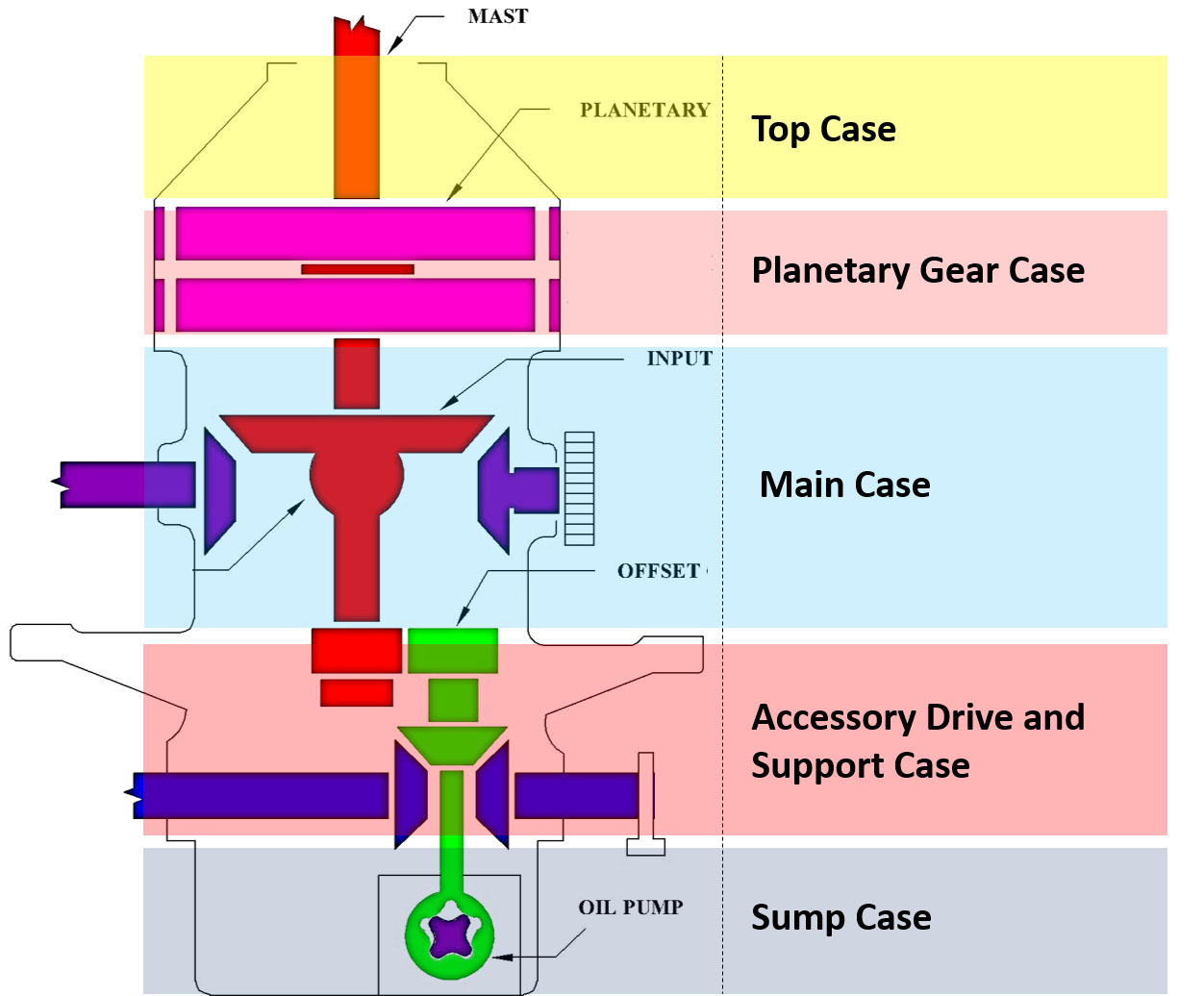
Figure 2: Main Sections of a typical helicopter main gearbox/ transmission.
a. Top Case
It is also called as upper case in most of the helicopter transmissions. It serves as the support for the main rotor mast when installed or for lifting the transmission when necessary. Also, the top case houses a vent that relieves internal pressure within the transmission.
b. Planetary Gear Case
The planetary gear case or commonly called as ring gear case is the only transmission case which is made of steel. It houses the first and second stage planetary gear sections which give required gear reduction to the main rotor mast.
c. Main Case
The main case of the transmission has the provisions for the main input quill and output blower quill or any other outputs necessary to drive other accessories.
d. Accessory Drive Case and Support case
The accessory drive or support case house the tail rotor output quill, transmission hydraulic pump and tachometer drive quill and transmission oil pump. The support case of the transmission allows the transmission to be attached to the airframe at different positions.
e. Sump Case
It is the lowest part of a transmission and houses the oil pump, drain valve and chip detector(s) of the oil system. Sump case may have oil level sight gauge as well to show the level of oil in the transmission assembly which is essential to be checked on daily basis. Along with internal oil filter and the oil pump inlet screen of oil lubrication system may also be present in this part.
Transmission Quills;
The transmission contains a varied number of quills depending upon its specific design. Most important and commonly found on most of the transmissions are as under:
a. Main Input Quill
The main input quill is located on the aft side of the transmission facing towards engine normally. The engine transmits power to the transmission through the main driveshaft and the main input quill. A freewheeling unit or clutch located in the main input quill operates automatically, engaging to allow the engine to drive rotor or disengaging the idling engine from transmission during autorotational descent.
b. Tail Rotor Drive Quill
The tail rotor drive quill is located on the aft side of the transmission. The forward part of tail rotor driveshaft is attached to a splined coupling which is part of the tail rotor drive quill.
c. Hydraulic Pump and Tachometer Drive Quill
The hydraulic pump and tachometer drive quill is located on the right side of the transmission sump case. The quill has pads for two hydraulic pumps and the rotor tachometer generator.
d. Fan Drive Quill
The fan drive quill is located on the forward side of the transmission. This quill transmits power from the transmission input bevel gear to drive the air distribution blower (fan).
e. Alternator Drive Quill
The alternator drive quill is normally located on the left side of the transmission. The purpose of this quilt is to transfer power from the input bevel gear of the transmission to drive the alternator.
Main Rotor Mast Assembly;
The main rotor mast assembly is a tubular steel shaft fitted with two bearings, which support it vertically in the transmission. Mast driving splines are engaged with transmission’s upper stage planetary gear. Splines on the upper portion of mast provide mounting for main rotor and control assemblies.
Main Drive Shaft ;
The main drive shaft is installed between an adapter on engine output shaft and the freewheel coupling of the transmission input drive quill. The flexibility of couplings is provided by sliding an inner coupling in splines of an outer coupling to accommodate movement of transmission on pylon mountings. Similar like arrangements may be available in transmissions to provide flexibility to the main drive shaft.
Tail Rotor Drive Shaft;
It comprises of various sections which transmit power from the transmission to the tail rotor through two gearboxes. The shaft sections are identical and are supported by hanger assemblies on the tail boom and engine deck.
Tail Rotor Driveshaft Hanger Assembly;
Different numbers of hanger assemblies connect and support tail rotor driveshaft along the top of the tail boom and engine deck. Each assembly consists of couplings on a short, splined shaft, mounted through a single-row sealed ball bearing in a ring-shaped hanger equipped with two mounting lugs for attachment on a support fitting.
Intermediate Gearbox;
The intermediate gearbox is located on the tail boom at the end of the vertical fin. The gearbox provides any degree of change in direction of tail rotor driveshaft. It consists of a case with a gearbox quill at each end. The case may be fitted with a breather-type oil filler cap, an oil level sight gage and a drain plug equipped with a chip detector which activates warning lights on the pilot and gunner caution panels and the miscellaneous controls panel when excessive metal particle contamination occurs. The input and output quills have flexible couplings for attachment of drive-shafts. Access is normally provided by a cover with quick-release fasteners.
Tail Rotor Drive Gearbox;
A gearbox at the top of tail boom vertical fin provides ninety-degree or any desired change in direction of drive and speed reduction between the input drive shaft and the output shaft on which the tail rotor is mounted. The gearbox consists of mating input and output gear quill assemblies set into gear case provided with a breather-type oil filler cap oil level sight gage and a drain plug with a chip detector. The input quill has a flexible coupling for attachment of driveshaft. Control linkage may be attached to the left side with a control rod extending through the rotor shaft.
 What Are Seaplanes And Their History Of Development ?
 Interesting Facts You Never Knew About Commercial Aircrafts And Aviation
 Extended Ground Proximity Warning System - EGPWS
 Airspace Classifications And The Air Traffic Control Services
 How An Instrument Landing System ( ILS ) Works
 EFB (Electronic Flight Bag)
 All About Aviation Fuels