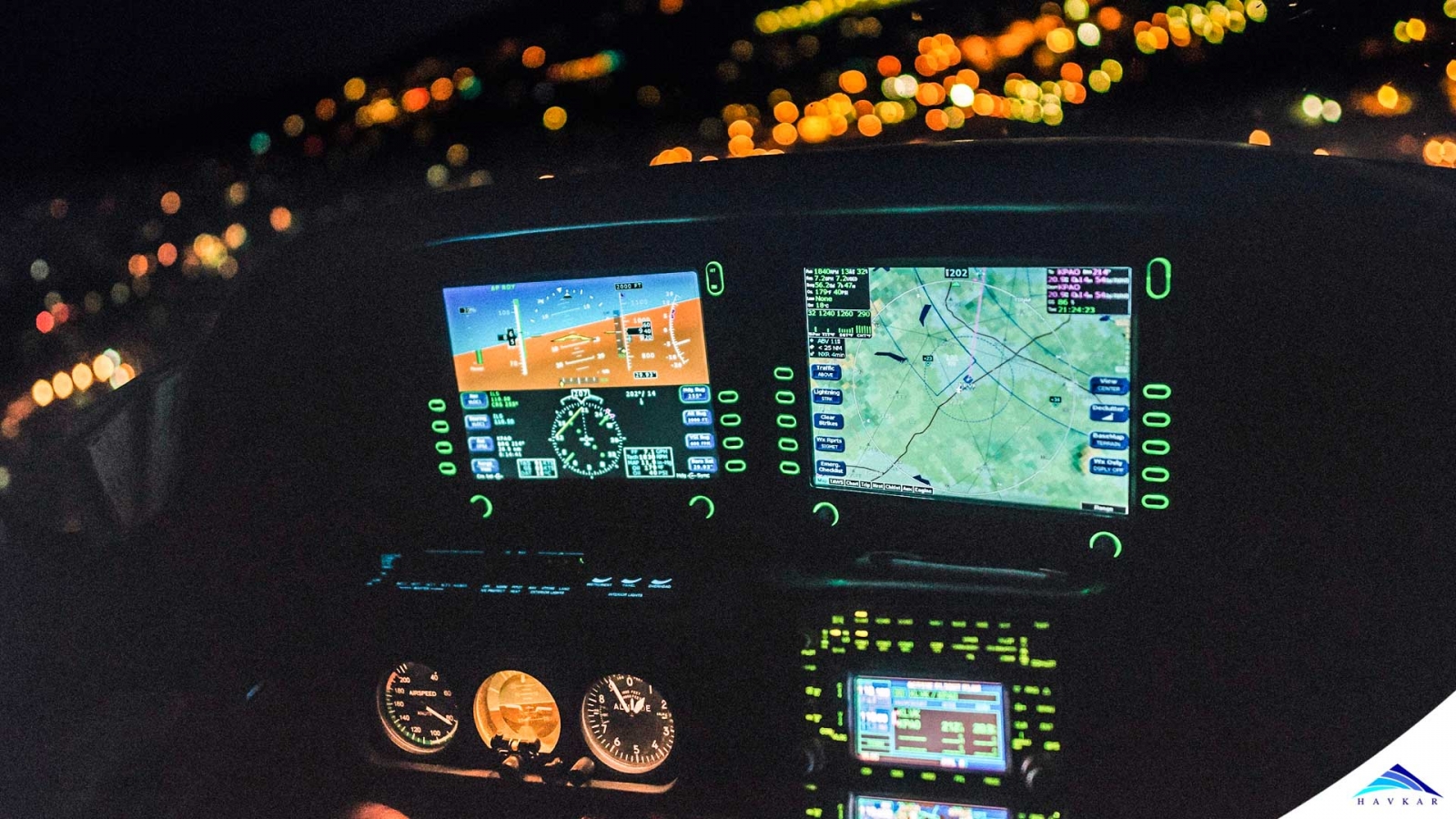
This can be as simple as following visually identifiable landmarks on ground, during a daytime flight with good weather condition.
However, when visibility is not granted, due to a cloudy sky or a night flight, or even if the travelling distance is simply too large for visual flight, some aid is required for the pilots: Navigation Systems.
The Beginnings;
The most simple navigation system used in aircraft is the magnetic compass, as the one shown in Figure 1. The compass works by aligning its internal magnets to the north pole of the Earth’s magnetic field. By doing this, the compass card rotates and gives a visual indication to the crew of the aircraft heading.
Usually, there are a lot of errors associated with the compass indication. However, since the magnetic compass does not need energy to work nor any ground infrastructure to be used, it is found in every type of aircraft, whether it is a small piston-prop or a huge jet airliner, and it is intended mainly as an emergency instrument.
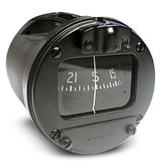
Figure 1 - A typical aircraft magnetic compass
In the beginning of aviation, a map and a magnetic compass were the only instruments available for pilots to navigate. Using, then, their airspeed information and measuring time, they could estimate their current location and, ultimately reach a destination. This technique is called dead-reckoning and, as one can imagine, it is very susceptible to cumulative errors. However, radio waves started being used to aid aircraft navigation, which made it much more precise.
Radio Navigation;
After World War II, a radio-based navigation system started to appear all over the world: the VHF Omnidirectional Range, or simply, the VOR. It consists of a ground-based transmitter which emits radio waves in the range of 108.00 to 117.95 MHz in all directions.
A receiver installed on the aircraft detects the incoming signal from the VOR station and an instrument in the panel gives to the pilot indication of the station location.

Figure 2 - A VOR Station
The military counterpart of the VOR is known as TACAN. Despite being a military system, there is one feature of the TACAN that is largely used by civilian aircraft as well. This feature is the Distance Measuring Equipment (DME). The DME system is used to calculate the distance between an aircraft and a DME antenna on the ground, and the value is displayed on the flight deck.
The DME has become so useful for the civilian aircraft that it has been installed in civilian VORs over the years. The DME and the VOR together provide full information for the crew to know where their aircraft is located.
To assist on landings, the Instrument Landing System (ILS) was developed. This system uses radio waves to provide the crew with lateral and vertical guidance during approach phase. The lateral transmission is called Localizer, and the vertical broadcast is the Glideslope.
The Localizer signal is received by an aircraft antenna and, with that, an indication on the flight deck is given to the crew in order to maintain alignment of the aircraft with runway centerline. Meanwhile, the Glideslope transmission is received and it is used to generate visual guidance so that the pilots can bring the aircraft down following the correct slope to the touch point on the ground.
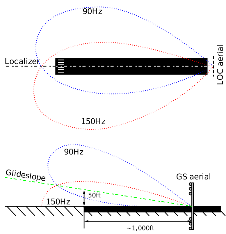
Figure 3 - Localizer and Glideslope Beams
Global Positioning System;
Differently than the radio-based navigation systems, which depend on stations installed on ground, another form of navigation aid largely used by aircraft all over the world is the Global Positioning System, the GPS. The GPS system is comprised of a constellation of satellites orbiting the Earth. The orbits are defined in a way that at any given time on any location on Earth at least four satellites will be at a minimum of 15° above the horizon.
Each satellite emits a signal and the aircraft receives it. Based on the travel time of the signal from the satellite to the aircraft and on the information of the exact location of each the satellite, the aircraft position can be calculated very precisely.
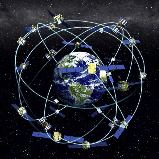
Figure 4 - Illustration of GPS satellites Constellation
Currently, the GPS accuracy is in the order of 20 meters for horizontal position, while the vertical estimation has a little bit more error. For navigation from one point to another, this precision is more than enough. However, for approaches, a more accurate estimation is required. The Wide Area Augmentation System (WAAS) reduces the error to only about 8 meters.
The WAAS is made of several ground stations that receive GPS signals from satellites and, after processing it, transmit to aircraft the correction information for position. Aircraft that have GPS receiver capable of using the WAAS can be landed on a large number of airports that do not have any ground-based approach system.
Self-contained Navigation;
Long-range navigation, which is typical of large aircraft, can also be performed with good precision without the need of external equipment. The Inertial Navigation System (INS), or, in more modern versions, the Inertial Reference System (IRS), does not require any external signal to operate.
The system uses accelerometers to continuously measure the aircraft accelerations and, based on that, it can calculate its velocity and, further on, its displacement. Associated with a starting location informed by the crew on system initialization, the position of the aircraft can be obtained in every instant.

Figure 5 - A modern IRS Unit
Final Remarks;
After mastering the flight mechanics, the engineers and aviators could devote their effort to make aircraft fly long distances. The use and improvement of navigation systems over the years have made the astounding accomplishment of travelling around the globe through air a relatively simple task.
 What Are Seaplanes And Their History Of Development ?
 Interesting Facts You Never Knew About Commercial Aircrafts And Aviation
 Extended Ground Proximity Warning System - EGPWS
 Airspace Classifications And The Air Traffic Control Services
 How An Instrument Landing System ( ILS ) Works
 EFB (Electronic Flight Bag)
 All About Aviation Fuels